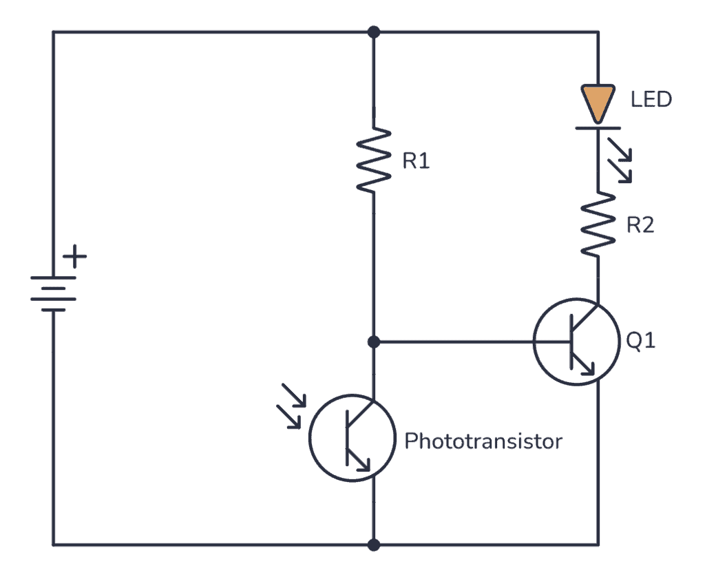
Phototransistor Circuit Circuit Diagram A typical simulation model for an NPN phototransistor circuit is shown below. Typical simulation model for an NPN phototransistor circuit. Your goal in this circuit is to construct a load line so that you can determine the photon flux (i.e., base collector voltage and current) that will produce switching behavior and saturation. At low photon
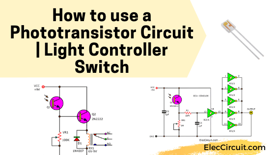
Read first for beginners: How do transistor circuits work. Simple phototransistor light controller circuit. This is Simple light controller circuit that is controlled light-activate. Which use the inverter gate IC-40106 as main components in compare and controlled switches, and common phototransistors as sensors. The Operation of switch has
Build Electronic Circuits Circuit Diagram
In this project, we will build the most basic phototransistor that is really possible. We will make it so that when light is shined on the phototransistor, such as from a flashlight, a buzzer will go off. So this circuit can act as a kind of light alarm circuit- if light is shone on the circuit, a buzzer will go off. Parts Needed. Phototransistor
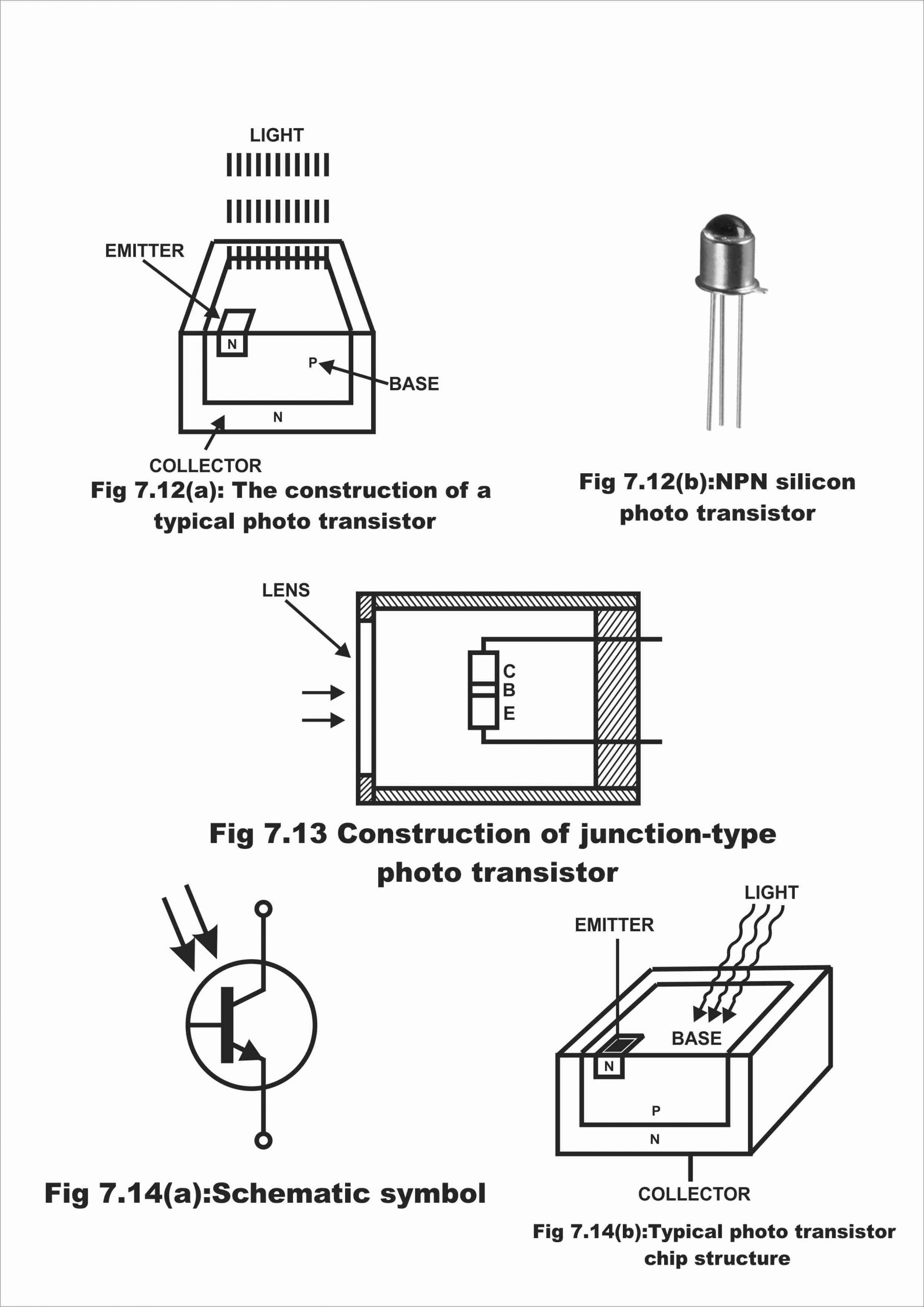
The response curve of a phototransistor has a broad wavelength range, from the near-ultraviolet, visible, and near-infrared parts of the electromagnetic spectrum. Therefore, the phototransistor can be used in various light detection circuits and devices. A typical phototransistor. The phototransistor's wavelength spectrum is shown below.

Build Electronic Circuits Circuit Diagram
Arduino With Phototransistor. A Phototransistor is a semiconductor device that's basically an NPN/PNP transistor but it doesn't have a base terminal lead. Instead, the junction is exposed to ambient light that hits the base of the phototransistor which develops a small voltage across the BE junction causing the transistor to conduct (switch ON).